
A dead bit
There are some 3D print jobs that require a focus on part strength. We’ve had a few projects in our time that have led us to trying a few different strengthening techniques in order to guarantee that a part will survive when dropped repeatedly or that it will stand up to loading conditions you’re planning to put it under. This study seems to show that there is very little difference in strength between expensive commercial 3D printing machines and low cost desktop machines. All you need is a little bit of time spent thinking and tuning the settings.
This article is a sort of checklist I've put together that’s really more tailored for FDM (or FFF) desktop 3D printers. While sections 1 and 2 deal with steps you can take immediately, sections 3 and 4 require a little bit more preparation and thought.
1.0 MODEL GEOMETRY

Surfaces can be offset then thickened to give stronger thin sections
1.1 THICKEN YOUR MODEL
Starting with the most obvious technique, thin geometry usually produces weak parts. This isn’t helped by the fact that desktop FDM printers struggle to attain a decent quality with thin parts of a print (eg. layer separation, warping and nozzle clash). Think about whether or not it’s possible to thicken the model geometry there. Sometimes it won’t be possible to change the geometry on 1 or 2 planes, but the third plane allows for some added material.
1.2 SCALE IT UP
Maybe this is also really obvious, but scaling up the part has the same effect as thickening all the geometry at the same time. Be careful to think about whether or not this will have consequences for any mating parts, or any functional elements of the design.
Fillets should be added to the bases of thin sections
1.3 SMOOTH TRANSITIONS WITH FILLETS/ROUNDS & ADD RIBS TO WALLS
During printing, it’s possible that the nozzles will knock thin parts off the print, causing displacement of the current layer. This makes thin parts even more wobbly. Use fillets, chamfers or blends to allow a sort of lead-in to a thin section, providing a stronger foundation for the thinner section.
2.0 LOOK AT YOUR PRINT SETTINGS
Source: Red Eye On Demand
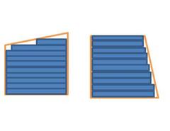
2.1 PRINT ORIENTATION
Do you have to print it standing up? Part are strongest in the X and Y axes, as the Z axis strength depends a lot on the properties of the layer. Sometimes the best orientation for printing is slanted diagonally, as the layers are usually not perpendicular to the direction of the load points or faces.
2.2 LAYER HEIGHT
When you print in smaller layer heights, the plastic is squashed down more, creating more surface area on the X/Y plane. Where the next layer isn't directly on top, a more squashed layer with higher surface area will have a higher contact area with the material. Higher contact area means higher layer adhesion, and the part is less prone to fail under tensile loading in the z axis. This means that a resolution of 100 microns will have stronger inter-layer bonds than the same print at 300 micron layer thickness.

2.3 INFILL % AND TYPE
This is another obvious one, but sometimes evades my thought pattern at first. Changing infill percentage, infill type and occasionally angle can help to strengthen the 3D printed part. We’ve read a bit about how it’s pointless to print anything over 60-70% infill, however we have a client who needs parts done at 100% infill as 75% is not strong enough. One thing to note is that any infill setting above 75% will most likely impact on the outer surface of the part.
2.4 PERIMETERS/SHELLS OR SHELL THICKNESS
Following on from infill, another strengthening option is to increase the number of shells or perimeters in the slicing settings. We’ve found that 2 or 3 shells are usually enough, but some applications where loads are high or extremely localised, it may require 4.
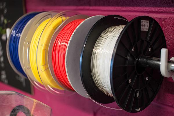
2.5 MATERIAL
While we prefer to print in ABS 95% of the time, there are a few options for materials on desktop 3D printers - each with different strength properties. While ABS is a strong and flexible plastic, PLA is hard but stiff. Sometimes a flexible material will be stronger or more resistant to shocks, but when geometric stiffness is required, PLA will be better. Remember that though PLA is hard, it is relatively brittle. Where extra durability is required, it is possible to print in Nylon. Taulman 618 is a great nylon filament for FDM printers, although a bit of extra machine setup is usually required.
3.0 POST-TREATMENT

3.1 EPOXY OR POLYESTER RESIN
Something that we’ve looked at recently is resin coating. For purposes when extremely accurate geometry is needed and sharp edges need to be preserved, this technique won’t be right for you. There are many different types of 2 part epoxy resin or polyester resin, each with different material properties and curing properties. Also, there will be a range of viscosities available. Don’t use 2 Part epoxy glue. It won’t work very well and produce a really lumpy finish.
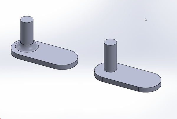
We use Polyester Clear Casting Resin as it’s thin enough to be spreadable all over intricate parts before it starts to cure. The resin starts to cure about 5 minutes after mixing, and takes about 24 hours to dry. It is also possible to use glass fibre shavings in the resin mix for extra strength, though this may impact on surface finish. The images below show the difference in the part (both parts were painted for a metal effect).

Before polyester resin coating

After polyester resin coating
After resin coating, we drop-tested two of the same model printed on the same printer with the same settings and material. The only reasonable difference was the resin coating. The resin coated part survived with no breakages at all, whereas the untreated part lost 5 or 6 different sections. We're going to continue to use this technique as our go-to strengthening method.
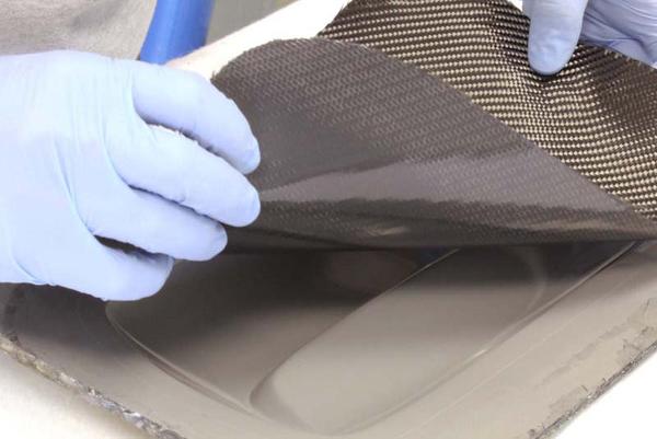
Source: Easy Composites UK
3.2 CARBON/GLASS FIBRE LAMINATION
Some parts may be suitable for carbon/glass fibre laminating. This isn't really suitable for intricate parts, as the part surface needs to be entirely wrapped in the fibre mesh; it's particularly suited to parts without holes or gaps. Once the part is wrapped in the fibre mesh, a layer of epoxy or polyester resin is applied over the mesh to solidify it in place. Bear in mind that this will add some extra thickness to the part.

3.3 HEAT TREATMENT
Although we've not tested this method, we've heard several reports that placing the part in an oven or using a heat gun/blowtorch to re-melt the outer surface of the plastic creates a stronger inter-layer bond. This sounds like a really dangerous method, as you risk melting the part completely, or distorting/warping certain features. If you're going to try this, start of at a lower temperature (and if using a heat gun, further away from the part then move gradually closer).
4.0 MOULD IT (OR MOLD IT, IF YOU'RE AMERICAN)
Jeshua of 3DTOPO demonstrates his method of "lost PLA" casting
4.1 PLASTER CASTING PARTS
Printing off your model in ABS or PLA allows you to mould. Investment (lost wax) casting is possible. To do this, print off your part as is, then cast the part in plaster of paris. You can then remove the original plastic print by heating the plaster cast in a furnace above 230C. You can then pour molten metal or plastic to into the mould cavity and let it settle. To remove to final cast part, the mould is destroyed with a hammer and the excess plaster is washed off. Something to bear in mind when experimenting with this method is that there will be some shrinkage of the part, so you'll need to scale the mould pattern up by 2-3%.

4.2 ROTO-MOULDING PARTS
An alternative to casting parts, a plaster or silicone mould can be used for rotational moulding. The strength advantage of using roto-moulding to create hollow parts lies in the lack of build layers, and a single crystalline structure for the whole part as it cools as one.
By pouring molten plastic/metal into the mould cavity, closing the mould and continuously rotating it on 2 axes, a hollow part can be achieved. There are numerous small/desktop roto-moulding machines available to buy, or you could build your own. The most common type of desktop roto-moulder consists of a central horizontal spinning X-axis to which is mounted a frame that spins on the Y or Z axis (rotates between them according to the X-axis). Usually they run off a single motor that control both axis via a gearing or pulley system. Each different mould shape will take some experimenting with rotation speed to ensure the molten plastic is spread over all the surfaces.

Source: StudioMyFirst